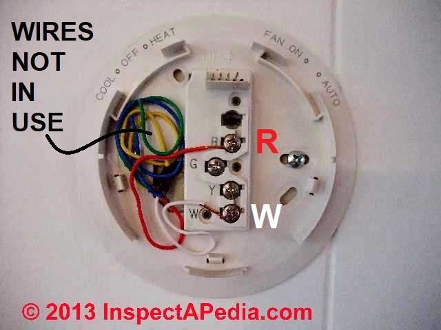
- Carrier Edge Thermostat Installation Manual Edge Pro Programmable Thermostat During thermostat installation provide sufficient excess wiring behind the mounting plate. Coil the wiring creating a service loop and place in mounting box or behind the wall to remove strain against the terminal strip.
- Description To replace the old thermostat and install the Carrier TP-PAC01-A Performance Edge, follow the steps described in the installation instructions on the 68 pages. This will allow the 7-day programmable thermostat to be installed correctly and proceed to device configuration.
- Online Library Carrier Edge Thermostat Installation Manual numerous times for their favorite books when this carrier edge thermostat installation manual, but stop stirring in harmful downloads. Rather than enjoying a good PDF next a cup of coffee in the afternoon, instead they juggled later some harmful virus inside their computer.
Below, you can find a troubleshooting manual for some Carrier Thermostat device models. For your convenience, they are present in the form of tables: they enlist the most widespread technical issues and provide detailed instructions for fixing the problems manually or via WiFi connection. The list of error codes for issue identification is also included.
Carrier Debonair-33CS Thermostat Troubleshooting
Carrier Edge Thermostat Manual Pdf
2012-05-21 azadara The ductless split units use a wireless stat that comes with the unit. The edge thermostat will not work correctly with the carrier ductless split systems. 2012-06-07 PexSupply Staff No where in this manual does it tell you how to turn the fan on if you want to run it independently (i.e. I went to install it and after removing my current Thermostat, a Carrier one, i noticed only two wires a V+ and a Vg. So according to the nest website, and the online support, my system is not compatible. Which to me is very hard to believe considering my current thermostat controls both Heat and Cooling, we have an AC unit and a Forced hot air.
| PROBLEM | SOLUTION |
|---|---|
| Display on thermostat not illuminated. | Check for 24 vac at the R terminal connection. Terminal R must be connected for proper thermostat operation. |
| Cooling will not energize. | Select COOL mode. Decrease cooling set point to 10 degrees below room temperature. Check for 24 vac at Y1 terminal. If present, thermostat is operating correctly and problem is with wiring or equipment. If 24 vac is not present, replace the thermostat. Check for Compressor Cycle per Hour Limit. Cooling may be locked out. |
| Heating will not energize. | Select HEAT mode. Increase heating set point to 10 degrees above room temperature. Check for 24 vac at W1/ O/B terminal. If present, thermostat is operating correctly and problem is with wiring or equipment. If 24 vac is not present, replace the thermostat. |
| When using 4 wires (R,G,W,Y), the cooling equipment tries repeatedly to turn on, but can- not. At times the display dims or disappears. | There is not enough power available. Connect a 270 ohm, 10 watt power resistor at the air conditioning equipment between terminals W and C (non-heat pump applications only). |
| When using 4 wires (R,G,W,Y), the heating equipment tries repeatedly to turn on, but can- not. At times the display dims or disappears. | There is not enough power available. Connect a 270 ohm, 10 watt power resistor at the air-conditioning equipment between terminals Y and C (non-heat pump applications only). |
| When controlling a heat pump, heat comes on during cooling cycle. | Configure thermostat for heat pump operation |
| When calling for cooling, both heating and cooling are energized. | The thermostat is configured for a heat pump. Configure the thermostat for non-heat pump operation |
| When controlling a commercial heat pump unit, unit runs in reverse or heating is always on. | Some commercial heat pumps require that Heat Pump Option on thermostat is turned OFF. |
Carrier AC Thermostat Troubleshooting

| SYMPTOM | WHAT TO CHECK |
|---|---|
| No LCD on temperature display | Check for 24vac between R and C at terminal connections. Both R and C must be connected for proper operation. |
| 'E2' on temperature display | Brownout condition or too low of voltage to thermostat. Double check wiring and check for 24vac between R and C. E2 will clear 15 sec after proper voltage is restored. |
| 'E1' on temperature display | Temperature sensor reading out of range. Check sensor for damage. If recycling power does not clear display, thermostat should be replaced. |
| 'Clean Filter' on temperature display | After the selected number of hr of blower operation 'clean filter' will display on LCD. |
| This is to remind the homeowner to 'check' filter. | |
| Press 'reset filter' button to clear display and reset timer to 0. | |
| “—“ on temperature display | If the outdoor sensor is open, not connected, or shorted will be displayed in place of outdoor temperature. |
| Cooling will not come on | Select COOL mode. Set desired temperature to 10'F below room temperature. Simultaneously press FAN and INCREASE TEMPERATURE buttons to defeat timers. Check for 24vac at Y (first-stage) terminal. |
| If present, thermostat is OK and problem is with equipment or wiring. If not present, replace thermostat. | |
| Heating will not come on | Select HEAT mode. Set desired temperature to 10‘F above room temperature. Simultaneously press FAN and INCREASE TEMPERATURE buttons to defeat timers. Check for 24vac at Y (first-stage) terminal (with heat pump) or W/W1 (with air conditioner) terminal. |
| If present, thermostat is OK and problem is with equipment or wiring. If not present, replace thermostat. |
Carrier 33AWCS1 Thermostat Troubleshooting
| Problem | Solution |
|---|---|
| Room Air Temperature Sensor Failure | If the sensor used to sense room air temperature, reads less than -45°C or greater than 65°C, it will be considered as failed and will display '-'. |
| Communication Failure | If the NUI does not receive CCN communication data from the CDU for 60 seconds, the display will show'E3' error code in the Temperature display zone and '-'in the Time Display zone. Under this condition the outside temperature will be blanked. 'E3' error code will be displayed and the other functionality will remain same. If this happens then check the communication cable between NUI and outdoor unit |
| Humidity Sensor Failure | If the sensor used to sense room Humidity reads less than 0 HR% or greater than 99 HR%, it will be considered as failed and will display '-' |
| EEPROM Failure | If the thermostat non-volatile memory (EEPROM) has failed, an 'E4' error will be shown in the room air temperature display. When this error is present and power is cycled to the thermostat all of the installer configurations, program schedule settings and user settings will be factory default values |

Carrier 33AW Thermostat Troubleshooting
| Fault Code | Fault |
|---|---|
| 3 | Enter water Temperature Thermistor (EWT) |
| 4 | Actual Refrigerant Temperature Thermistor BPHE |
| 5 | Outdoor Air Thermistor of GMC |
| 6 | Loss communication to NUI |
| 7 | NUI Room Thermistor |
| 8 | Unit Capacity Mismatch |
| 9 | Flow Switch error / Water Pump |
| 10 | EEPROM Corrupt |
| 11 | OAT high than Stop Heat |
| 12 | OAT low than Stop Cool |
| 13 | Loss Communication to RS485 (system configuration type=6) |
| 14 | Loss of Signal From CDU |
| 15 | Leaving water Temperature Thermistor (LWT) |
| 17 | CDU Outdoor Air Thermistor (TO) |
| 18 | G-Tr short circuit protection |
| 20 | Position Detection Circuit Error |
| 21 | Current Sensor Error |
| 22 | Outdoor Heat Exchange Sensor (TE) / (TS) |
| 23 | Discharge Temperature Sensor (TD) |
| 24 | Outdoor Fan Error |
| 26 | Other Outdoor Error |
| 27 | Compressor Lock |
| 28 | Discharge Temperature Error |
| 29 | Compressor Breakdown |
| 30 | Low Pressure Switch |
| 31 | High Pressure Release |
Carrier Base Series Programmable Thermostat Troubleshooting
| Problem | Solution |
|---|---|
| What if AUX HEAT appears on the display? | If auxiliary heat is on. you will see AUX HEAT indicator in the display. When it is on this means the system has determined that it’s too cold outside for your heat pump to heat the house without help, so it's getting help from the electric heaters. This happens automatically. |
| NOTE: This indicator does not mean there is a problem with your system | |
| What if E-IIeat appears on the display? | If the heat pump is not working properly, you can manually turn on the emergency heat for extra help in healing. You’ll know there’s a problem if the house can’t seem to get warm when it’s cold outside. |
| You want to avoid using emergency heat, though, because it’s the most expensive option. And. of course, if you suspect a problem with your heal pump, call your heating and cooling dealer immediately. |
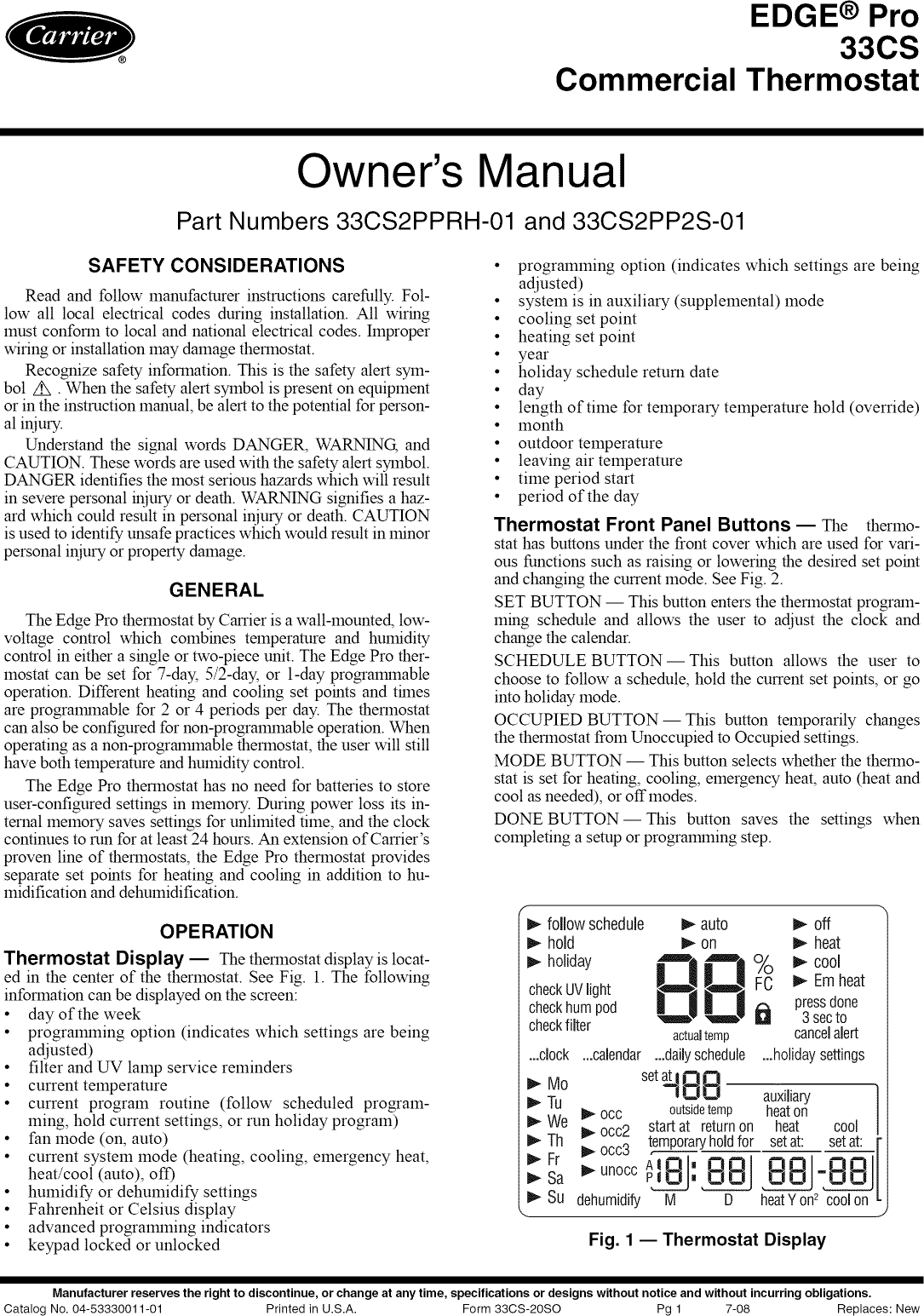
Carrier Edge Pro Thermostat Troubleshooting
| Error code | Solution |
|---|---|
| CODE El | If the display module and the equipment control module cannot communicate via two-wire connection, El will be displayed |
| CODE E2 | Not used |
| CODE E3 | If control cannot properly read outdoor temperature, and it is needed for proper operation, the display will indicate ” in the outdoor temperature location |
| CODE E4 | If internal memory fails, E4 will be displayed. Replace the thermostat |
| CODE E5 | If the thermostat cannot properly read humidity, E5 will be displayed. Replace the thermostat. If both Humidifi- cation and Dehumidification have been set to OF, the humidity value will be shown as when viewed from the humidity menu, but no E5 will be shown in the display |
Carrier 997 Programmable Thermostat Troubleshooting
| Problem | Solution |
|---|---|
| AUXILIARY HEAT indicator is displayed | The AUX HT indicator appears on the heat pump version of the thermostat only. It is displayed when your system is operating on auxiliary heat. |
| NOTE: This indicator does not reflect a problem with your system | |
| CLEAN FILTER indicator is displayed | The CLEAN FILTER indicator tells you when to clean or replace your system's air filter. Press the RESET FILTER button after cleaning or replacing the filter to turn off the indicator and restart the timer. |
| NOTE: This indicator does not reflect a problem with your system | |
| HOLD indicator is displayed | The HOLD indicator reminds you that your thermostat's comfort schedule has been overridden. This function will hold the current temperature settings indefinitely, so it can be used to hold an energy-saving temperature setting for several days if needed. Press the HOLD button to resume normal system operation. |
| NOTE: This indicator does not reflect a problem with your system | |
| You have a power outage | An internal power source eliminates the need to reprogram the thermostat after power outages. The comfort schedule you have entered will be maintained indefinitely. The clock will run for 72 hours |
| You have a system error message. The display may appear as follows: E2, or E3 | - indicates a problem with the indoor air sensor E2 indicates low line voltage E3 indicates a problem with the outdoor air sensor |
Similar Pdf to carrier 997 970210 3 installation
- * carrier programmable thermostat instructions
- * carrier thermostat 997 970210 3 manual free
- * carrier smart thermostat manual
- * carrier thermostat 997 970210 3 manual instructions
- * carrier thermostat control manual
- * carrier thermostat 997 970210 3 manual download
- * old carrier thermostat manual
- * carrier thermostat 997 970210 3 manual pdf
- * carrier thermostat manual
- * carrier digital thermostat manual
- * bryant programmable 997 970210 3
carrier 997 970210 3 installation Files for free and learn more about carrier 997 970210 3 installation . These Files contain exercises and tutorials to improve your practical skills, at all levels!
Carrier Edge Thermostat Installation Manual Online
You can download PDF versions of the user's guide, manuals and ebooks about carrier 997 970210 3 installation, you can also find and download for free A free online manual (notices) with beginner and intermediate, Downloads Documentation, You can download PDF files about carrier 997 970210 3 installation for free, but please respect copyrighted ebooks.
Copyright Disclaimer:
All books are the property of their respective owners.
carrier-thermostat-manual.com does not host pdf files, does not store any files on its server, all document are the property of their respective owners. This site is a Google powered search engine that queries Google to show PDF search results.
carrier-thermostat-manual.com is a custom search engine powered by Google for searching pdf files. All search results are from google search results. Please respect the publisher and the author for their creations if their books are copyrighted. Please contact google or the content providers to delete copyright contents if any and email us, we'll remove relevant links or contents immediately.