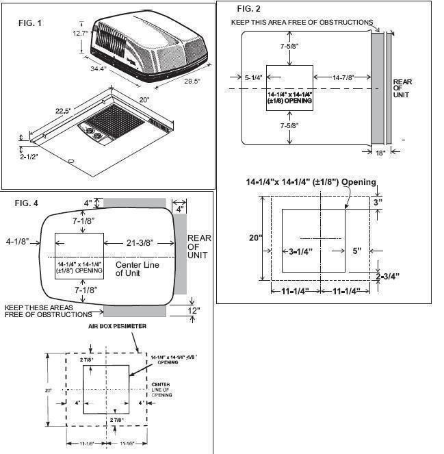
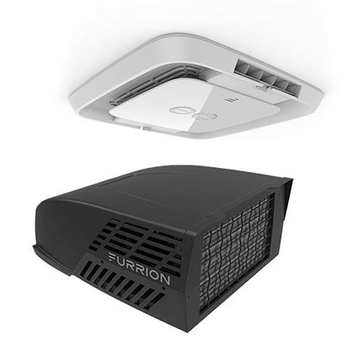
Dometic 15000 BTU Duo Therm Brisk 2 Air RV Air Conditioner Top Unit Black Dometic Duo Therm Brisk 2 Air Conditioner 15000 BTU Standard profile rooftop unit From the company that invented RV refrigerator, the Dometic Duo Therm Brisk 2 Air line is powerful enough to cool even the largest coaches. Since I had the reportedly fire hazard, I decided to call Dometic. I gave the lady the model number 600312.331 and the air distribution box number 330700. Of two possible boxes, one is metal, the other plastic. Mine is plastic, therefore I was told by Dometic NOT to install the heat strip as it would melt the plastic and could cause a fire. The Dometic model that you provided the number for shows up as the 'Dometic HP Air Conditioner' which is a variant of the Brisk II. I haven't worked on one of those yet. Attached is the wiring diagram for the Brisk II, which may match up with yours.at Moved To Our EasyStart Knowledge Bank. Find solutions to your wiring diagram dometic air conditioner question. Get free help, tips wiring diagram for a duo therm by dometic rooftop air conditiner.Series Penguin Series BRISK AIR Series QUICK COOL Series QUICK COOL Roof Top Air Conditioner USED WITH Part No. Electronic Kit Control The Dometic Air Conditioner Control is a sophisticated. 579 Series BRISK AIR 590 Series QUICK COOL 595 Series QUICK COOL Roof Top Air Conditioner USED WITH Part No. 2 INSTALLATION AND OPERATING INSTRUCTIONS GENERAL INFORMATION A. This air conditioner is designed for. The Dometic Corporation will not be liable for any.
Download Installation instructions manual of Dometic 57908.321 Air Conditioner, Heat Pump for Free or View it Online on All-Guides.com. This version of Dometic 57908.321 Manual compatible with such list of devices, as: 57908.321, 57915.322, 57915.336, 59516.601, BRISK AIR 595 SERIES
Brand: Dometic
Category: Air Conditioner , Heat Pump
Type: Installation instructions manual
Model: Dometic 57908.321 , Dometic 57908.521 , Dometic 57912.531 , Dometic 57912.532 , Dometic 57912.622 , Dometic 57912.631 , Dometic 57915.322 , Dometic 57915.331 , Dometic 57915.336 , Dometic 57915.422 , Dometic 57915.522 , Dometic 57915.531 , Dometic 57915.536 , Dometic 57915.541 , Dometic 57915.546 , Dometic 57915.622 , Dometic 57915.631 , Dometic 57915.731 , Dometic 57915.741 , Dometic 59016.521 , Dometic 59016.531 , Dometic 59016.621 , Dometic 59016.631 , Dometic 59516.303 , Dometic 59516.331 , Dometic 59516.336 , Dometic 59516.501 , Dometic 59516.531 , Dometic 59516.536 , Dometic 59516.601 , Dometic 59516.603 , Dometic 59516.631 , Dometic 59516.731 , Dometic BRISK AIR 579 SERIES , Dometic BRISK AIR 590 SERIES , Dometic BRISK AIR 595 SERIES
Pages: 12 (0.69 Mb)

Dometic


Dometic Brisk Air 2 User Manual Pdf

Related Products for Dometic BRISK AIR 579 SERIES
Related Manuals for Dometic BRISK AIR 579 SERIES
Dometic BRISK AIR 579 SERIES: Frequently viewed Manuals
Dometic Brisk Air 2 User Manual Instructions
User Manuals, Guides and Specifications for your Duo-Therm 579 Series BRISK AIR Air Conditioner. Database contains 3 Duo-Therm 579 Series BRISK AIR Manuals (available for free online viewing or downloading in PDF): Installation instructions manual, Installation & operating instructions manual .
Duo-Therm 579 Series BRISK AIR Installation & operating instructions manual (8 pages)
Pages: 8 | Size:
Duo-Therm 579 Series BRISK AIR Installation instructions manual (17 pages)
Pages: 17 | Size:
Duo-Therm 579 Series BRISK AIR Installation & operating instructions manual (16 pages)
Pages: 16 | Size: